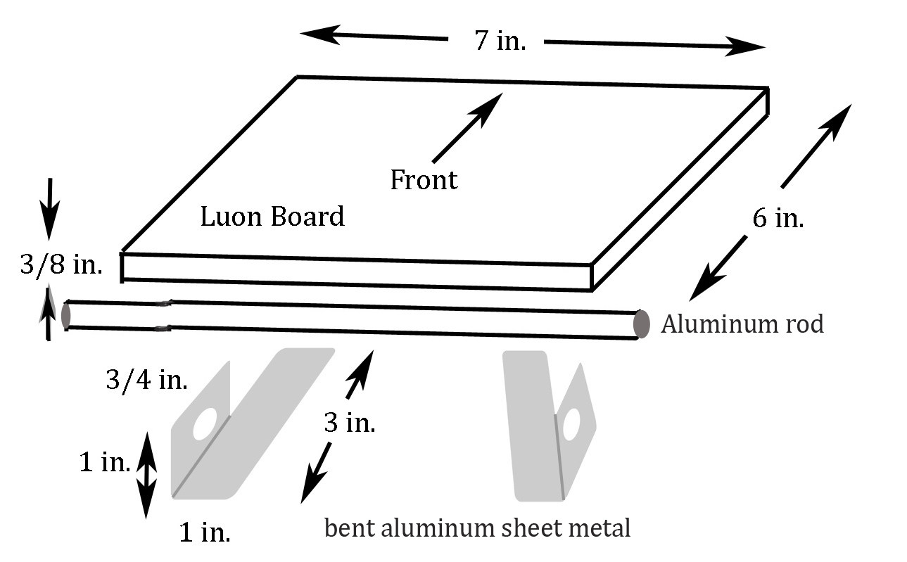
Welcome to the third lab in E5, where you will fabricate parts for your group's robot in the Machine Shop in the basement of Papazian (next to Hicks). A sketch of the components (luon plywood and aluminum sheet) is shown here (right-click to save or print):
A reminder of the robot groups :
| Lab A | Lab B | Lab C |
Group A1:
|
Group B1:
|
Group C1:
|
Group A2:
|
Group B2:
|
Group C2:
|
Group A3:
|
Group B3:
|
Group C3:
|
|
Group B4:
|
The assembly process set forth below is less a cookbook than guidance. Feel free to find better ways to do things than described here. The goal is a working robot that has the capability to pull itself or push itself along the ground with a 3-motor articulated arm.
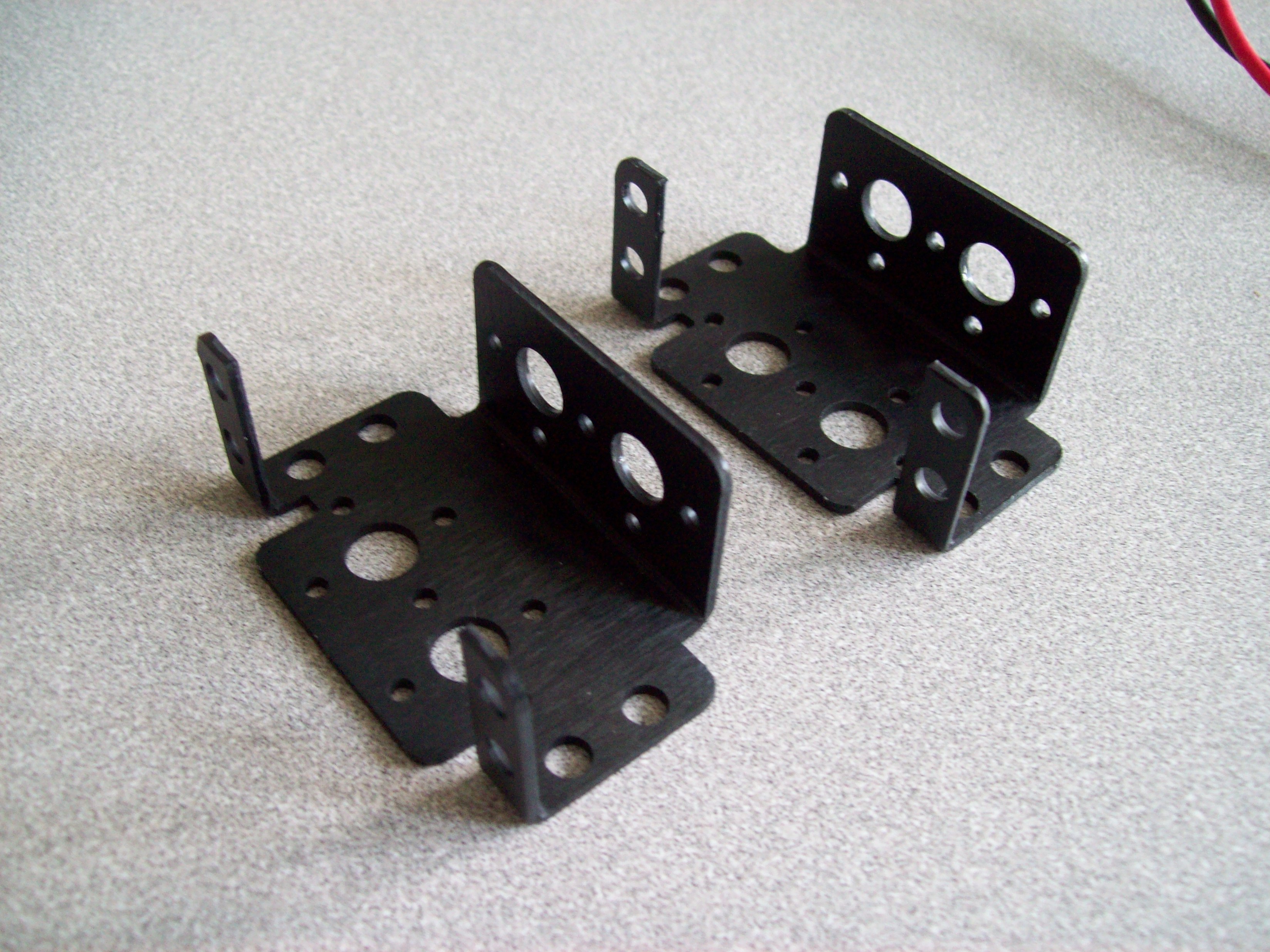
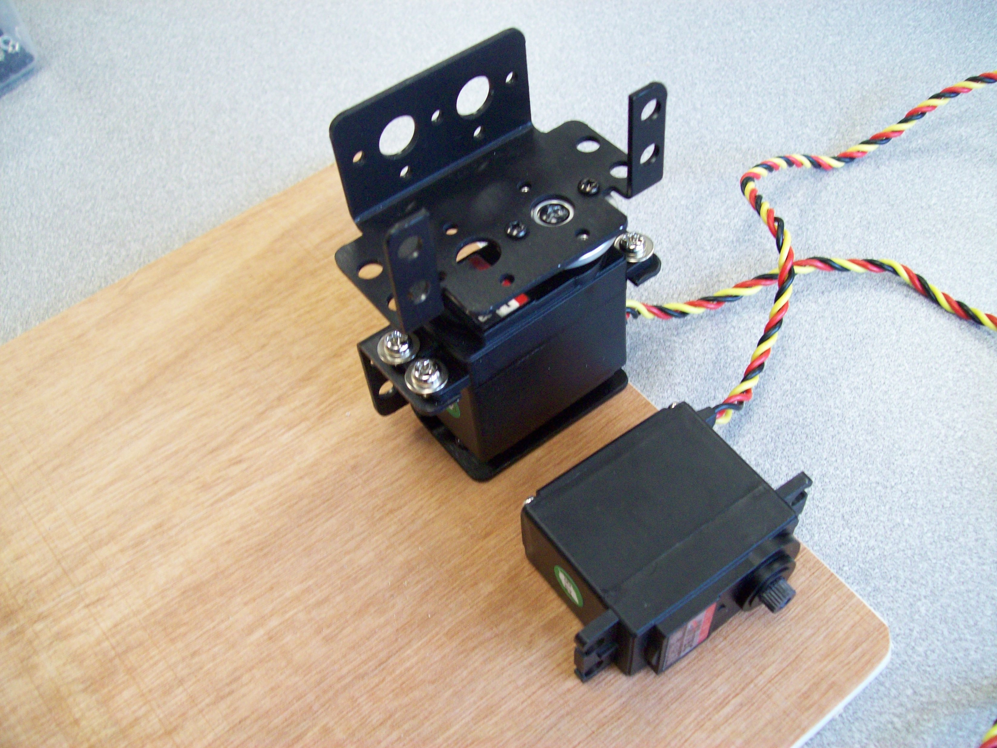
Start will selecting two multi-purpose servo brackets (ASB-04 or ASB-24):
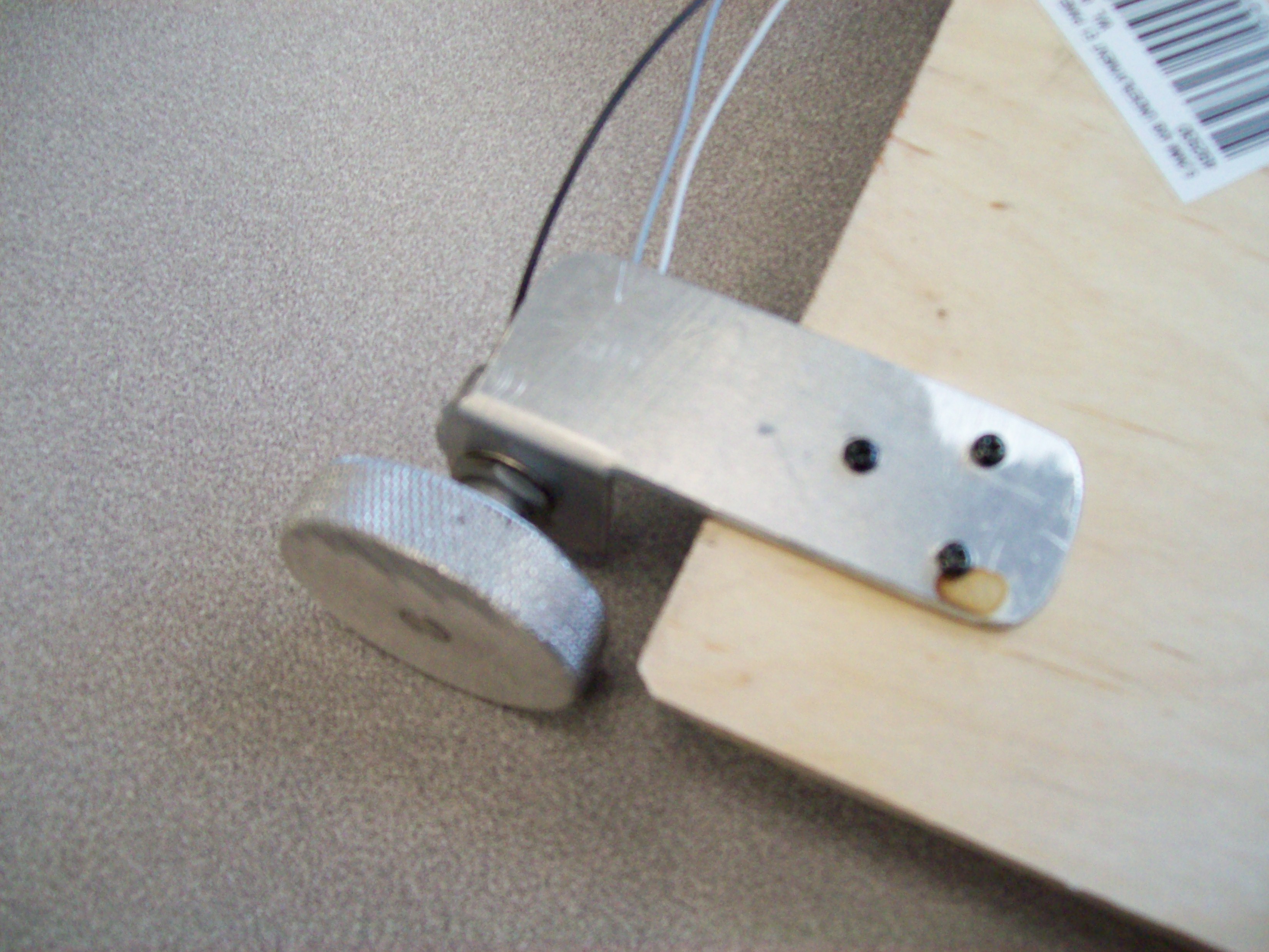
Using small wood screws (or through holes with machine screws & nuts), affix the rear wheel assemblies so that the outside of the wheel is even with the side of the board, leaving about 5 mm spacing to the back edge of the board (a push and turn will drive the wood screws right in without a pilot hole):
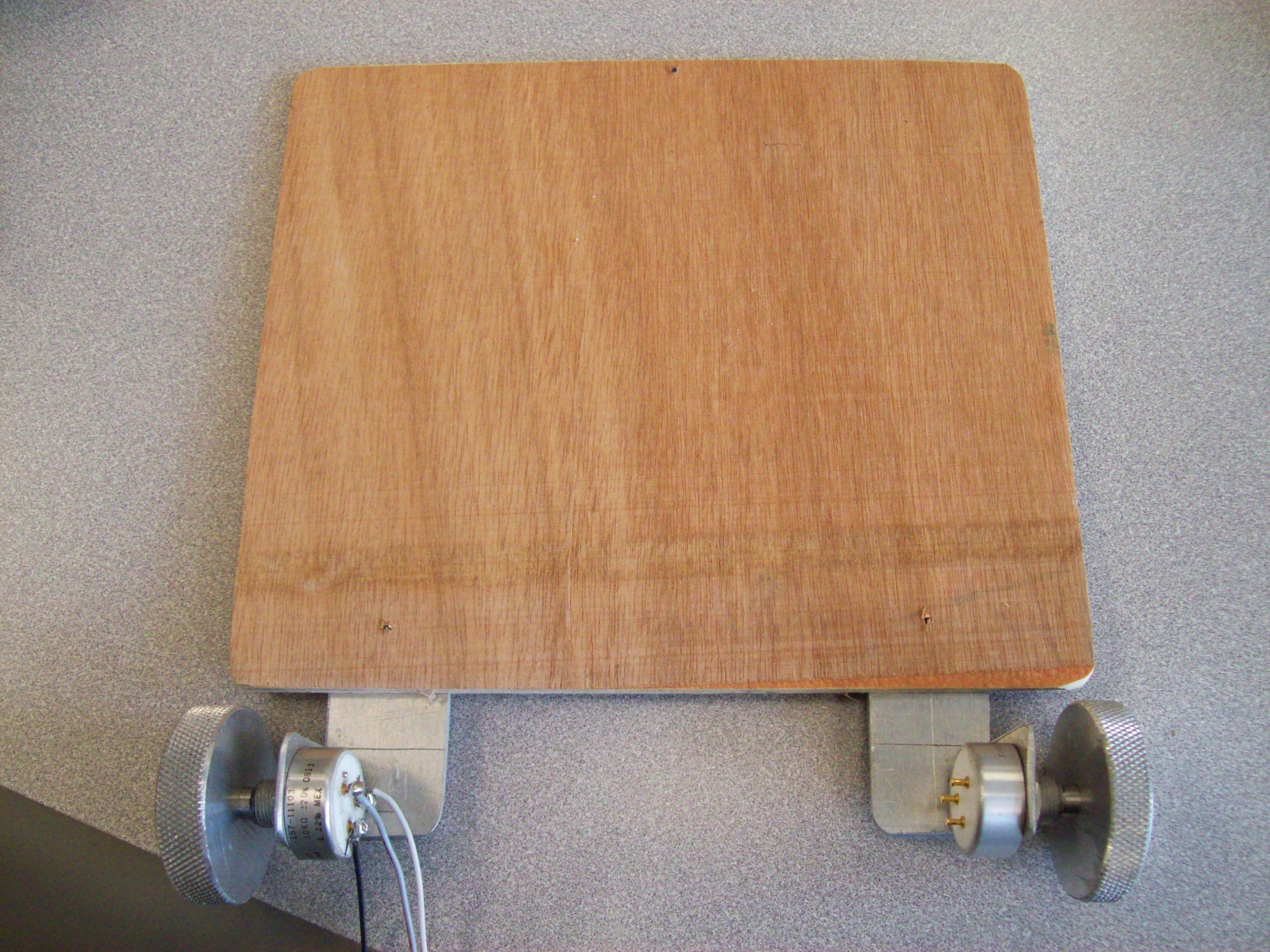
Do this on both sides, so that when the board is turned right-side up, it looks like this:
Using the small wood screws and a Philips screwdriver, affix one right at the forward edge of the robot board, centered:
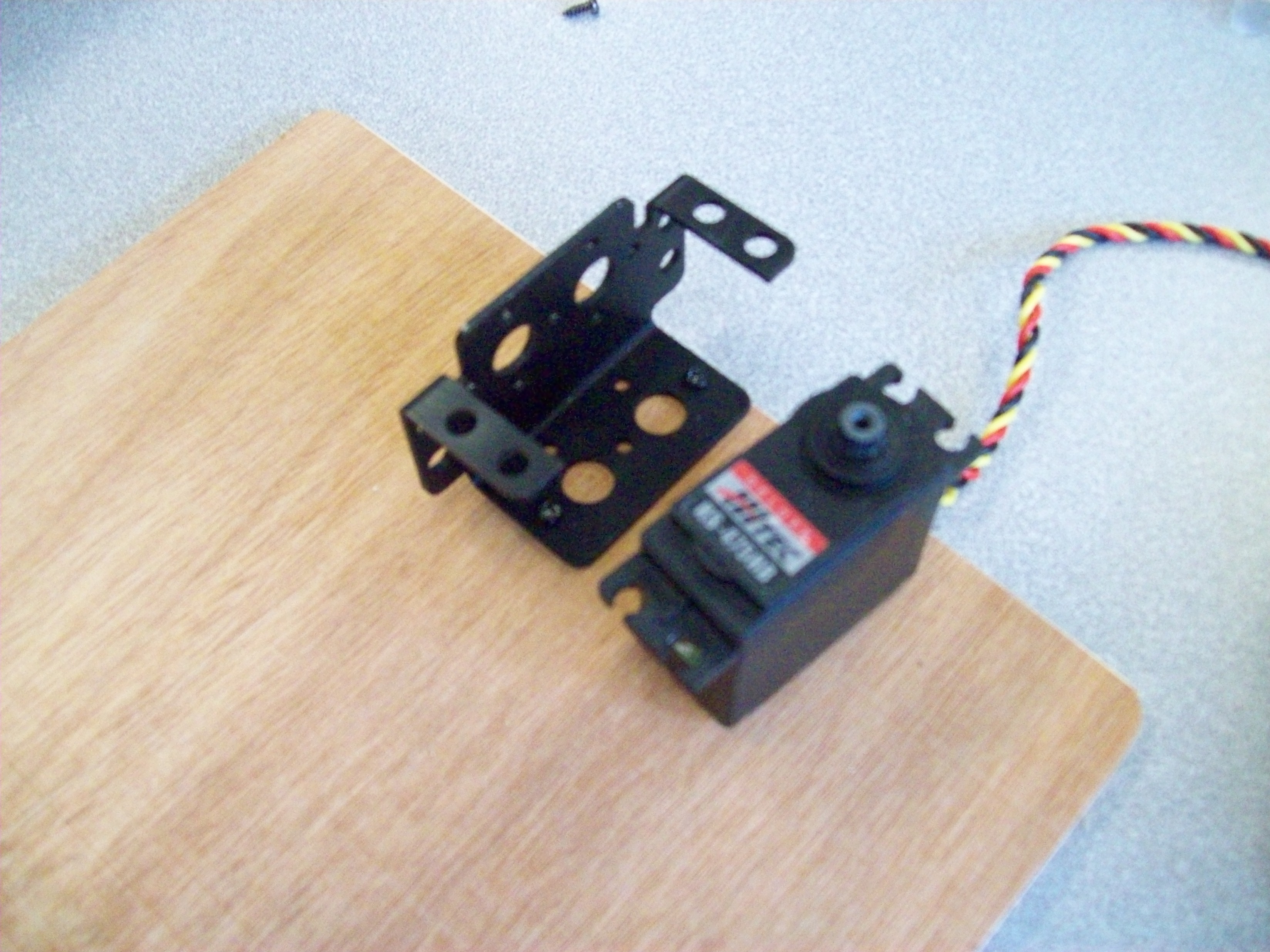
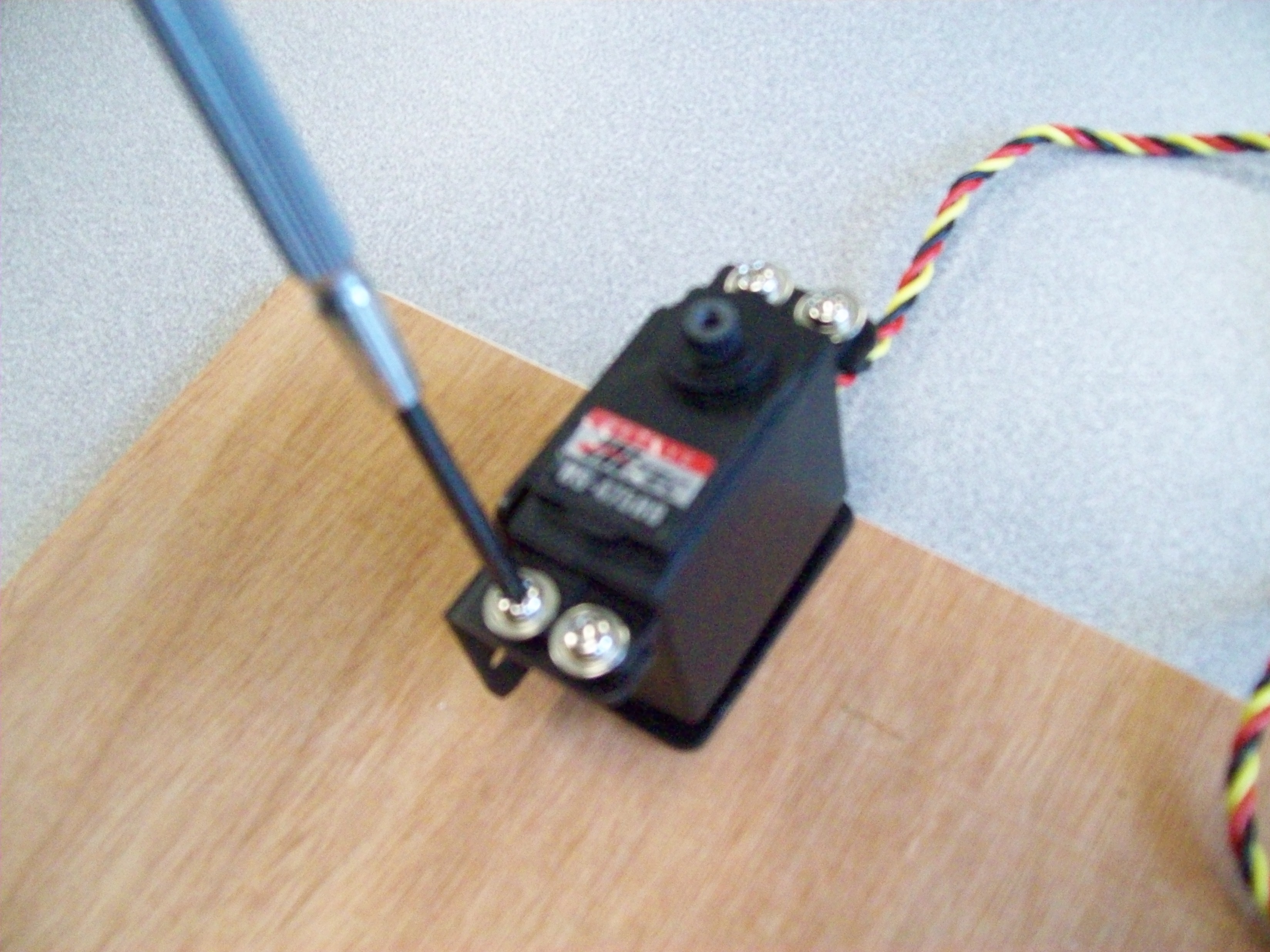
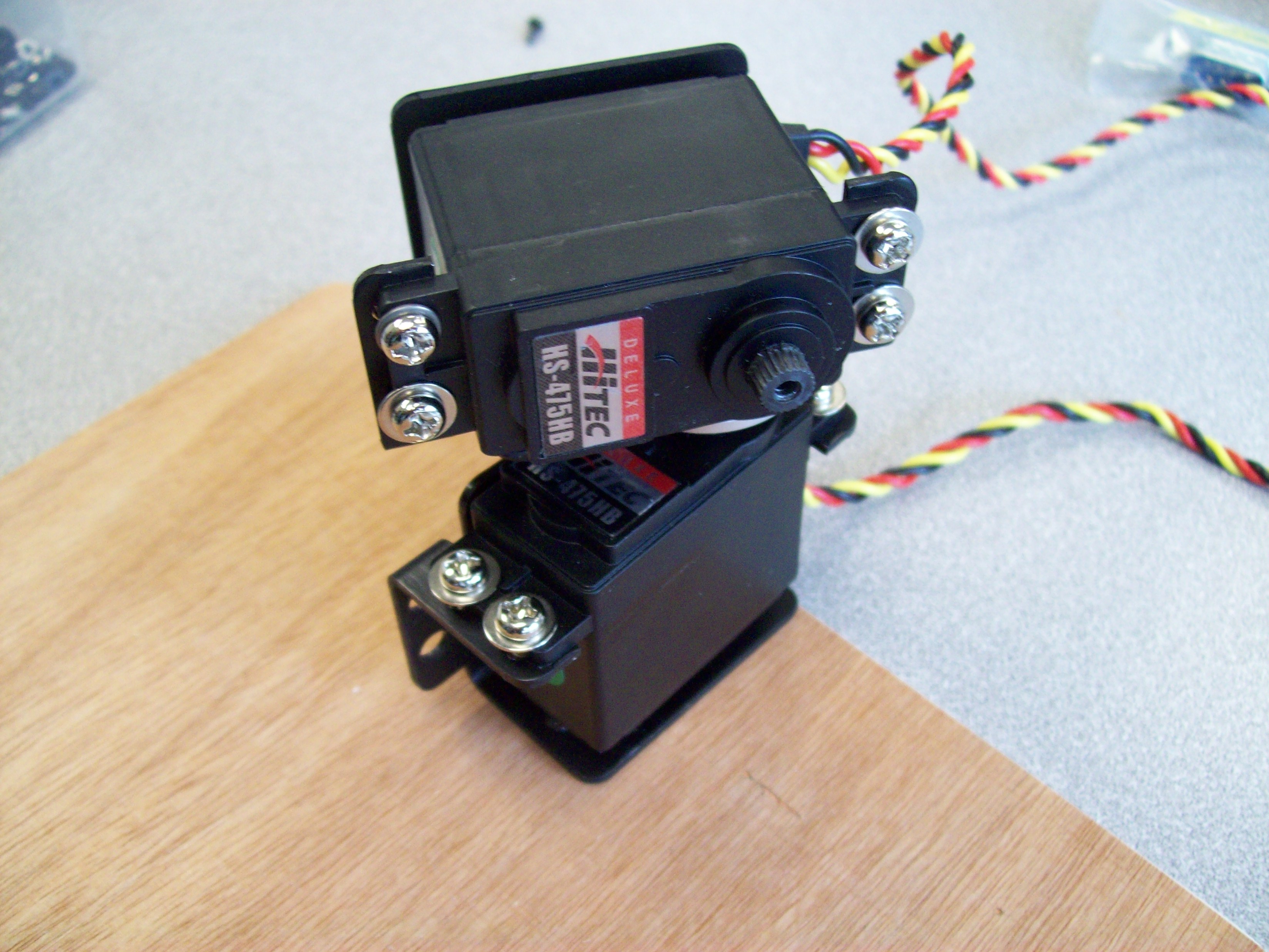
Mount the first servo, which will eventually steer the robot left and right, in the bracket as shown (two 4-40x5-16 machine screws with washers and nuts will be enough):
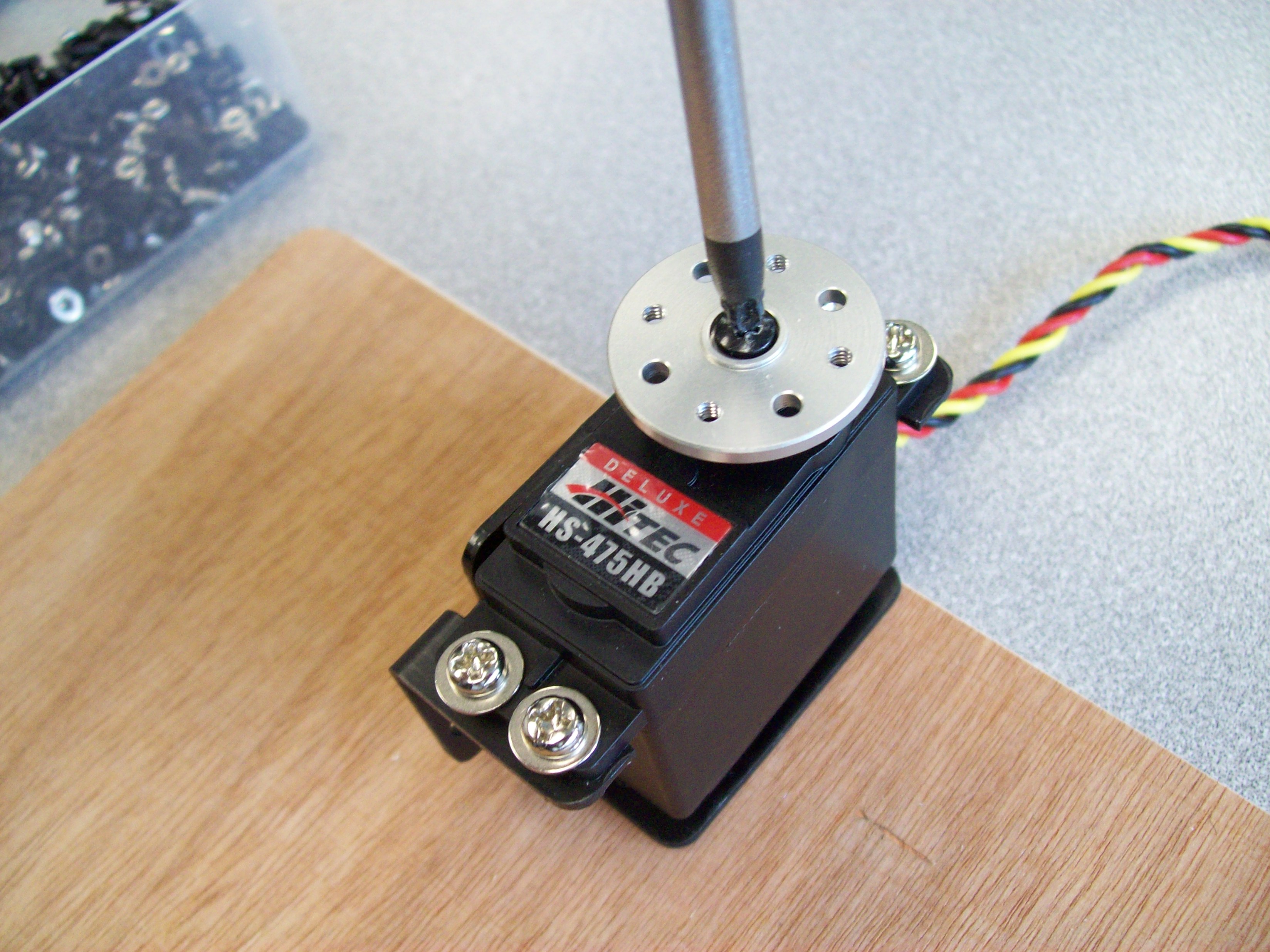
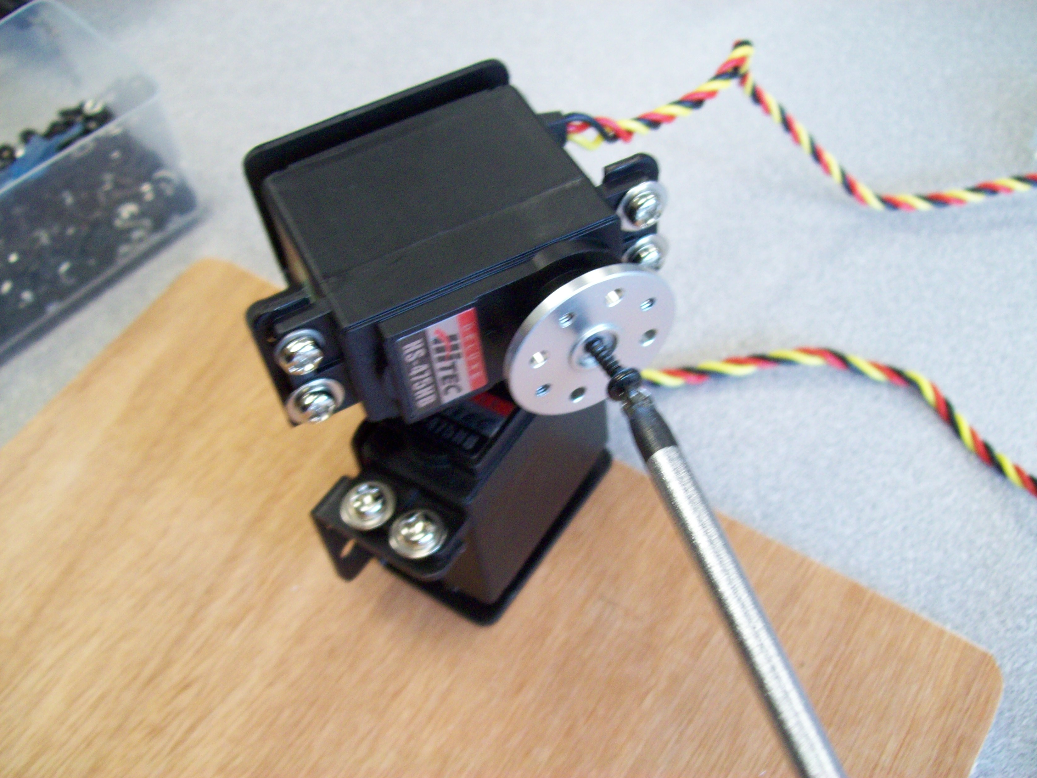
Use a center screw to affix a metal disk (HMSH-02) to the servo:
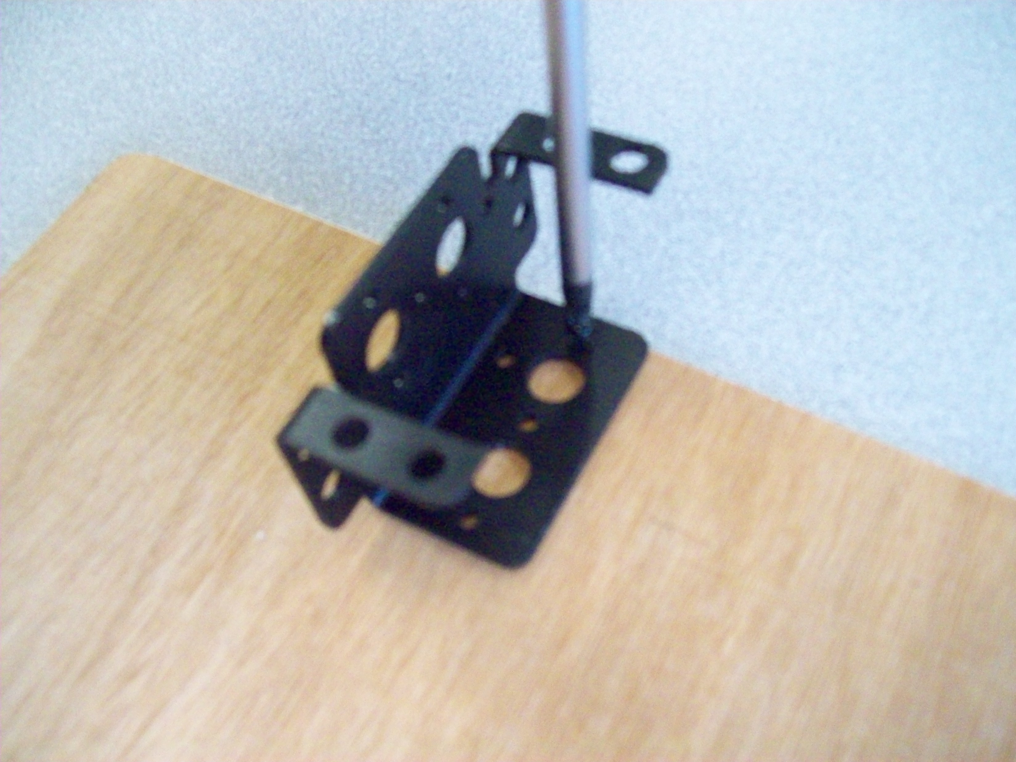
Mount the second bracket using the forward large hole in the orientation shown:
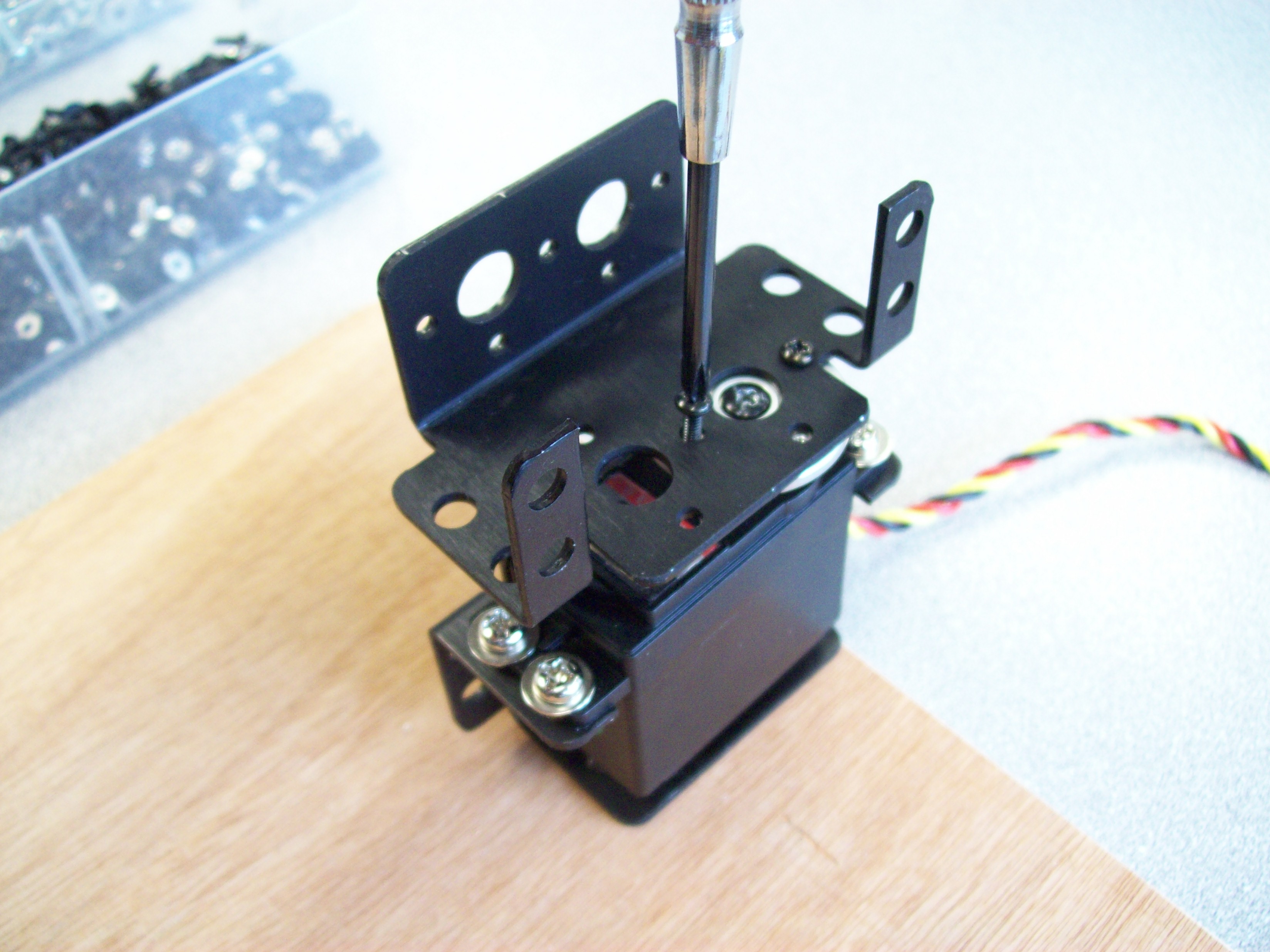
The second servo motor, which will lift the arm up and down, will go into this top bracket as shown, using the small 2-56x3/16 screws. Make sure the range of swing of the servo is centered about the forward orientation as shown:
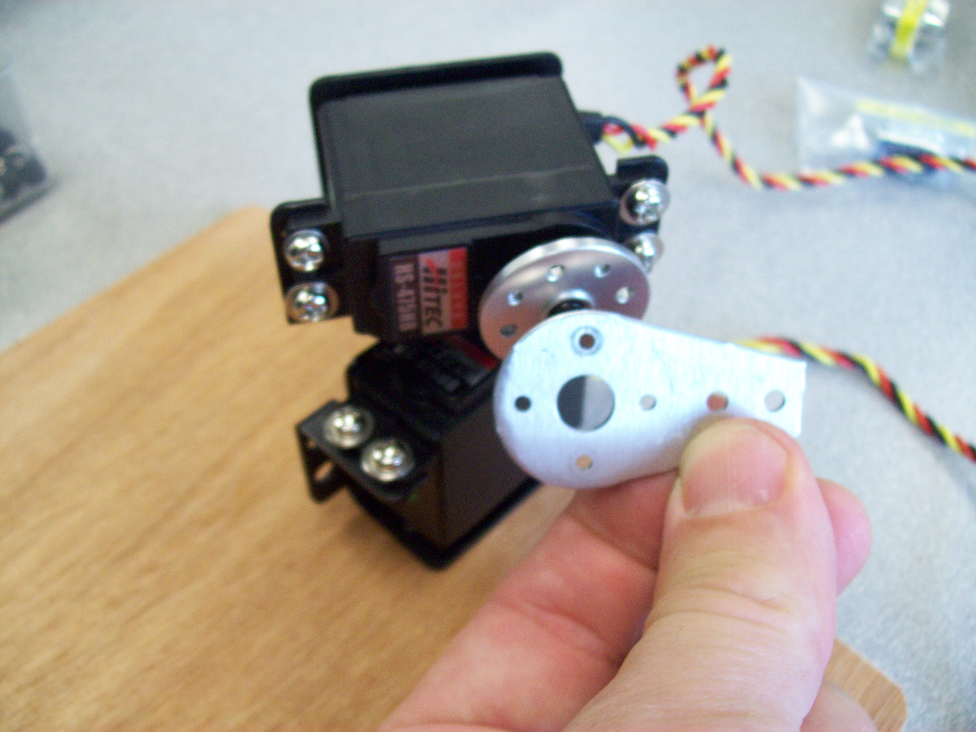
As before, use a center screw to affix a metal disk (HMSH-02) to this second servo:
Onto this second disk, mount an ASB-19 bracket, making sure that full clockwise of the servo puts the bracket aiming toward the edge of the board:
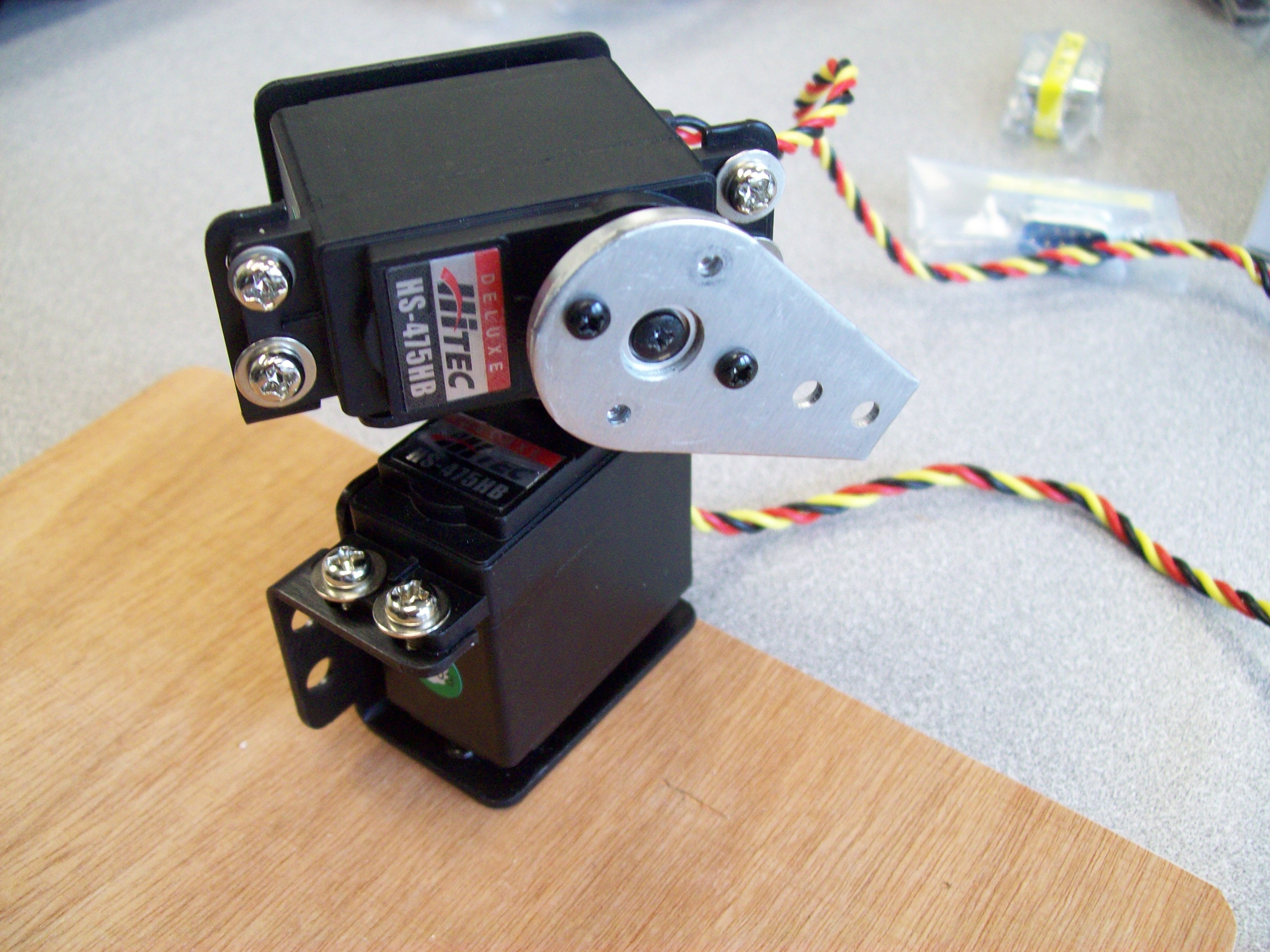
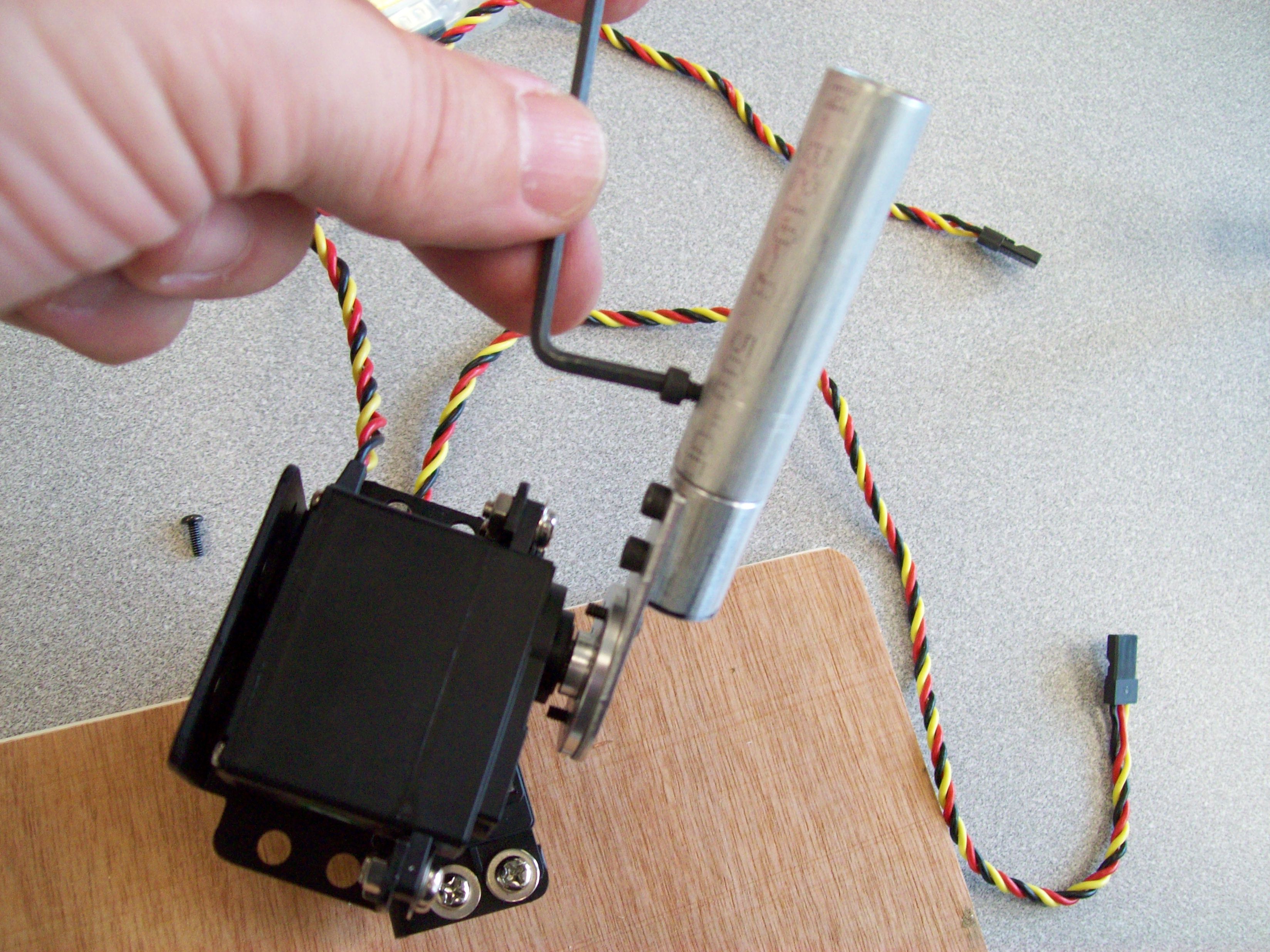
Locate a HUB-09 and affix it to the bracket using two large Allen-head machine screws with an Allen wrench:
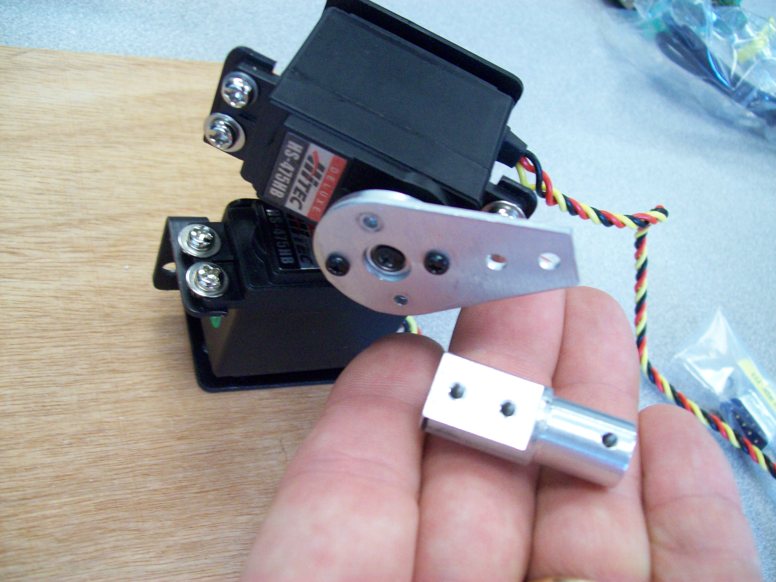
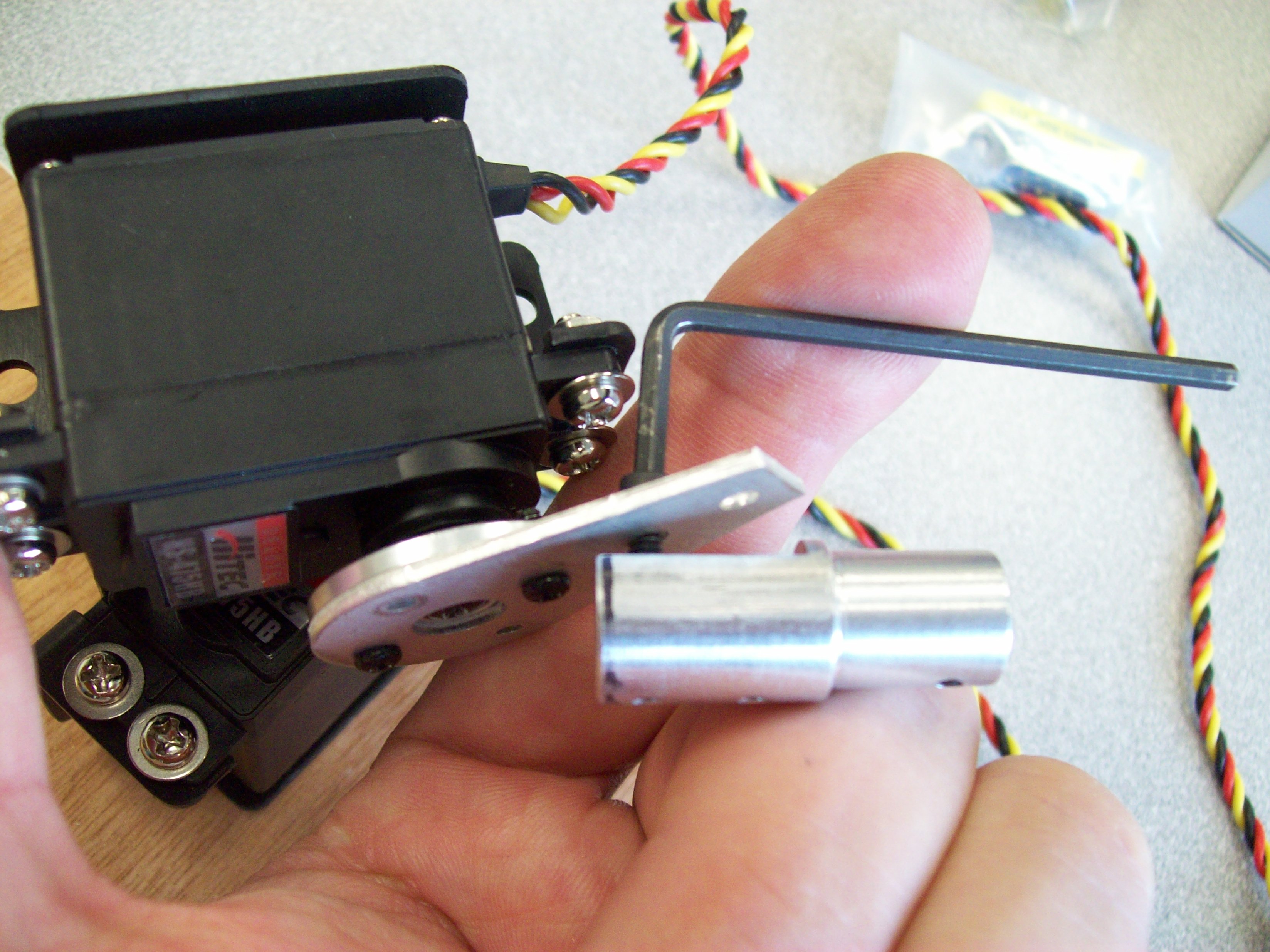
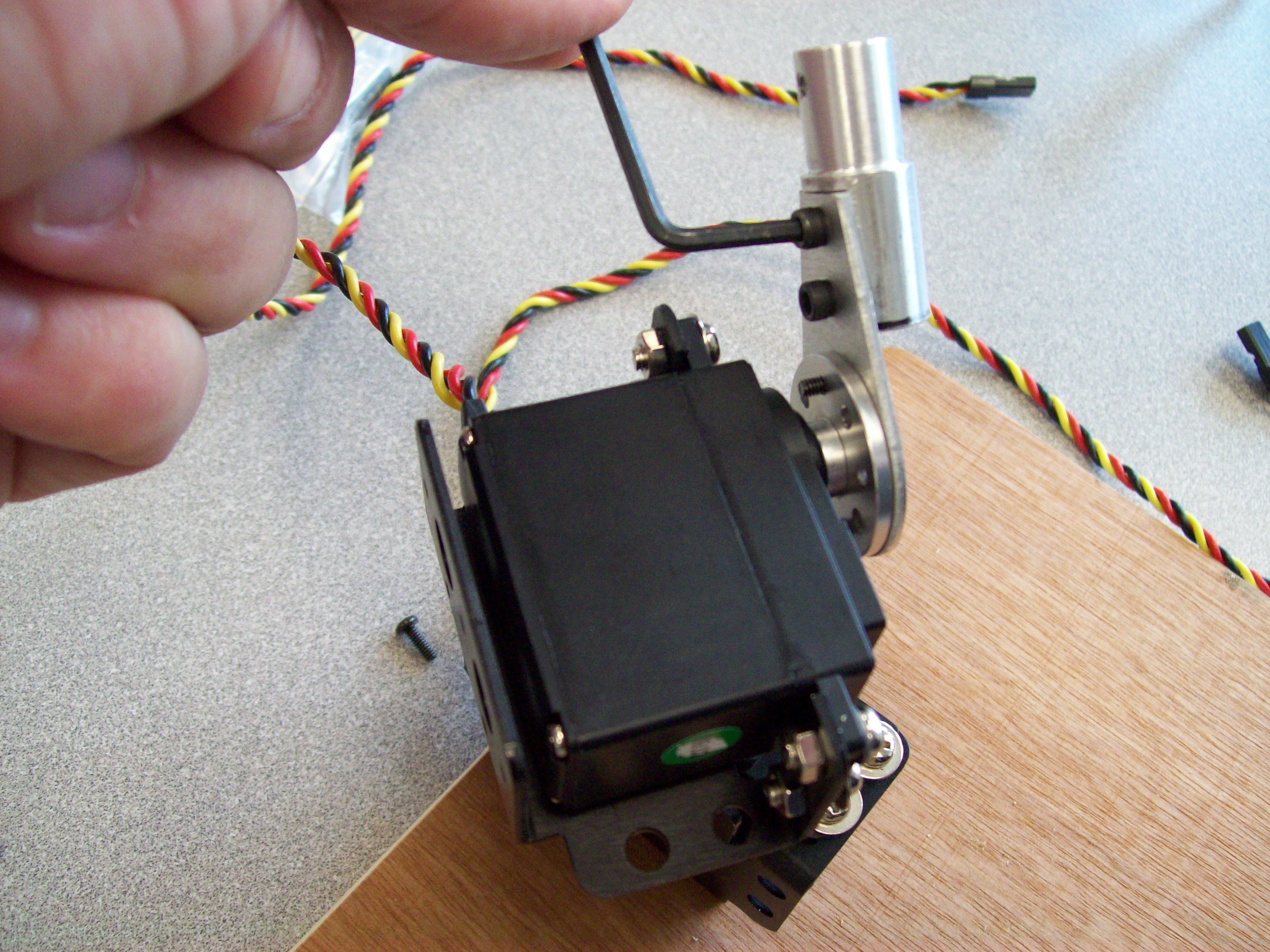
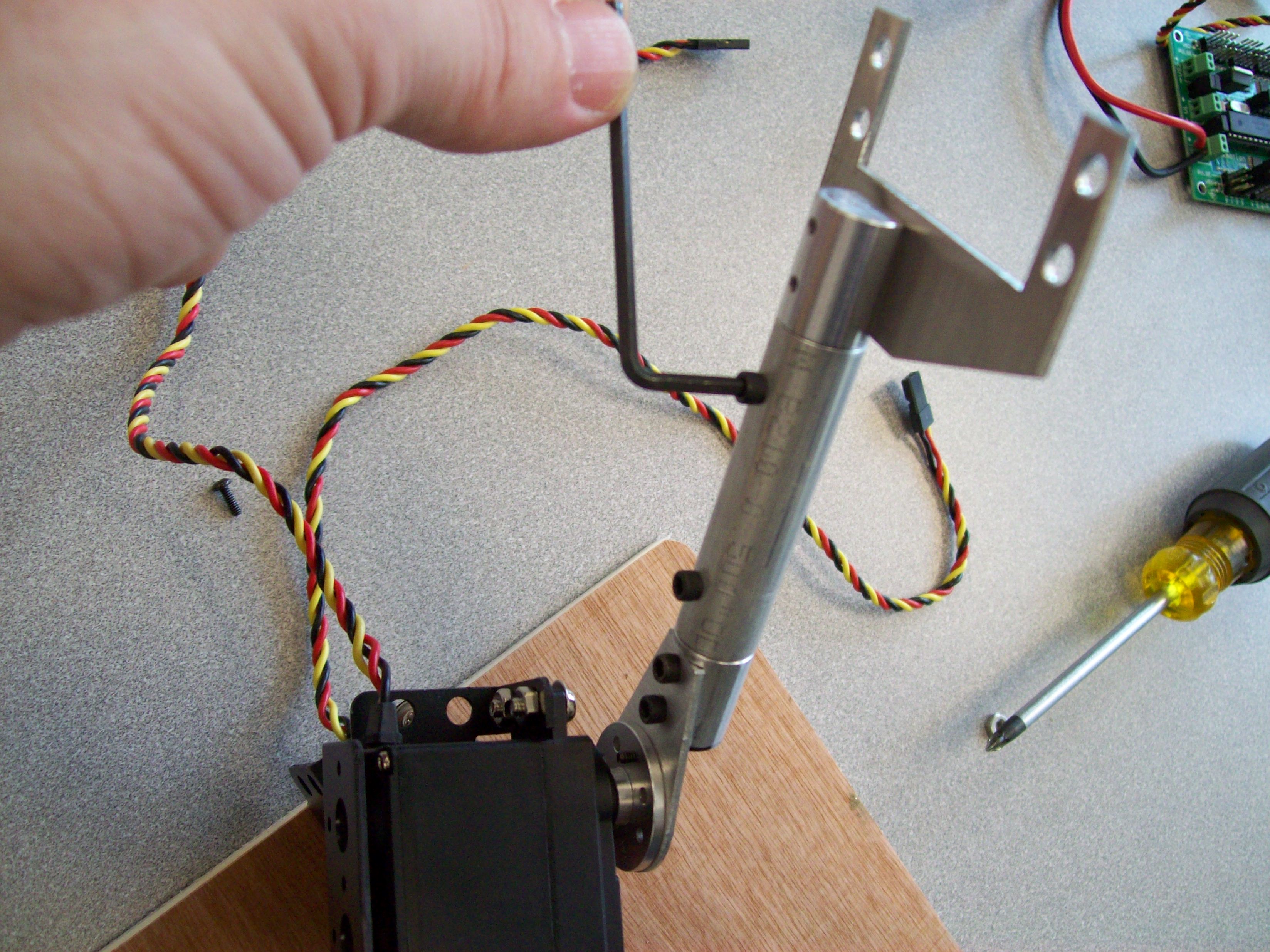
Using the same Allen-head screws, affix a 2-in. Tube to the HUB-09 end:
Find another HUB-09 and affix a servo bracket using Allen screws:
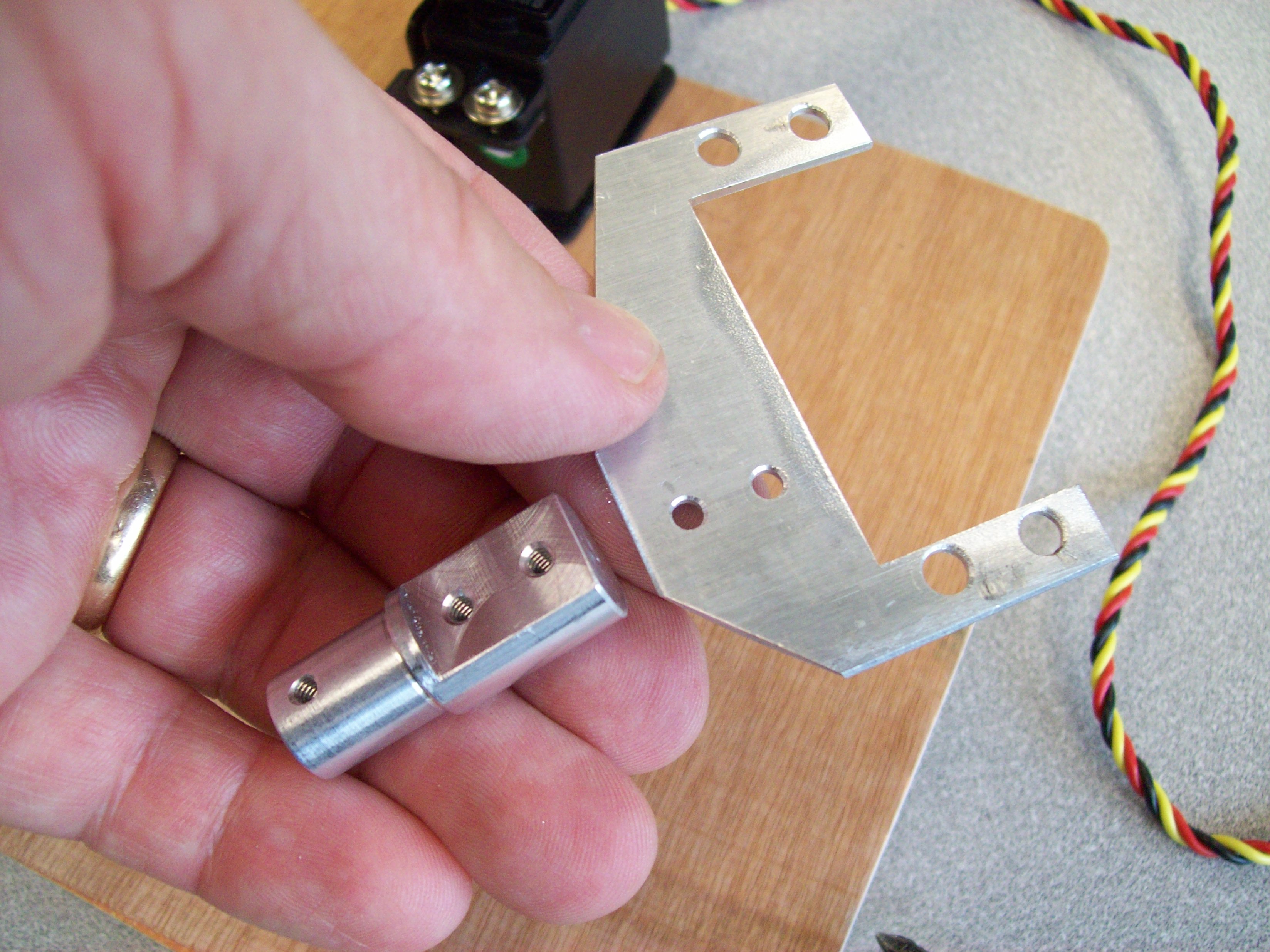
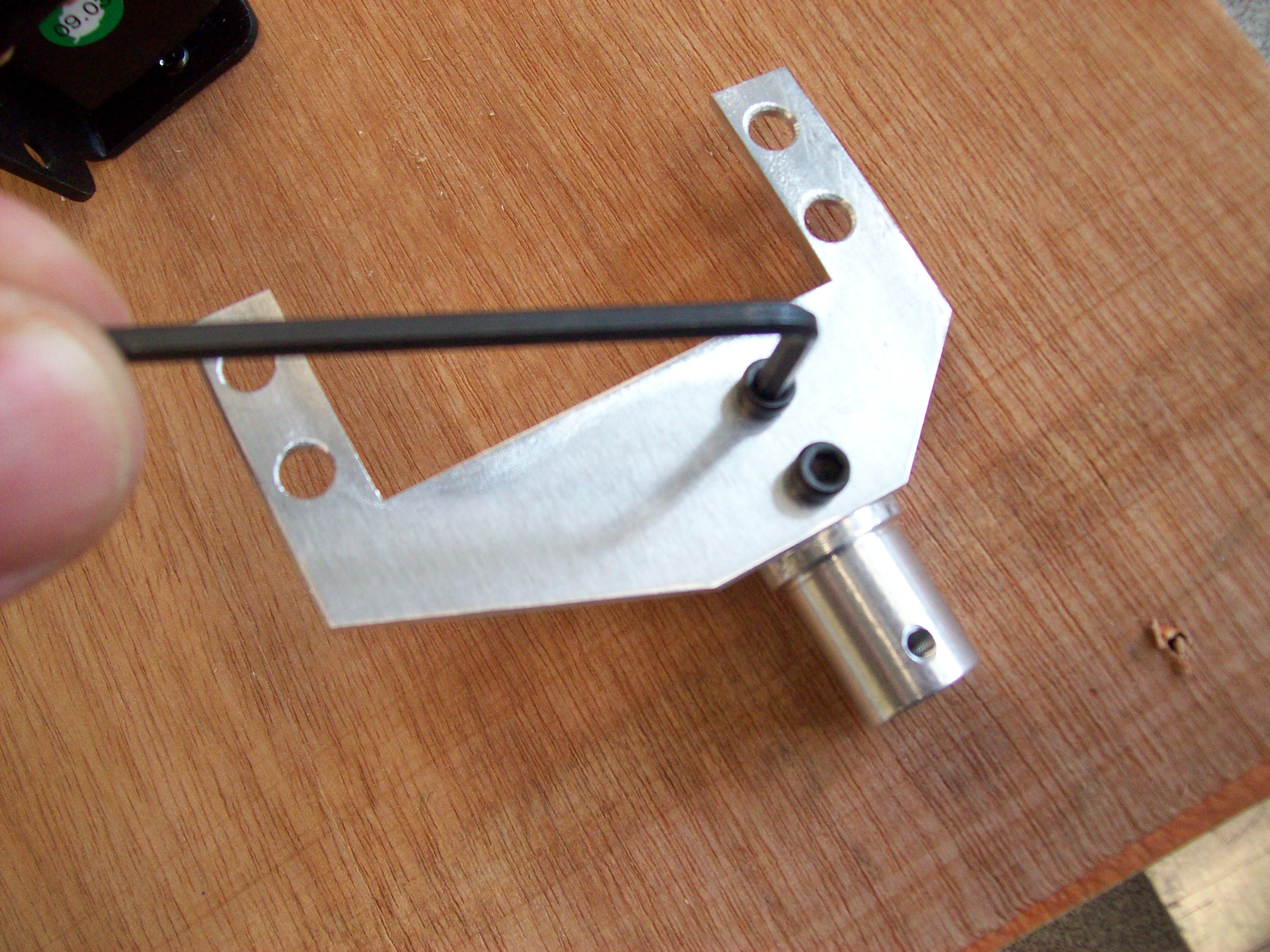
Put the bracket assembly onto the other end of the 2-in. Pipe:
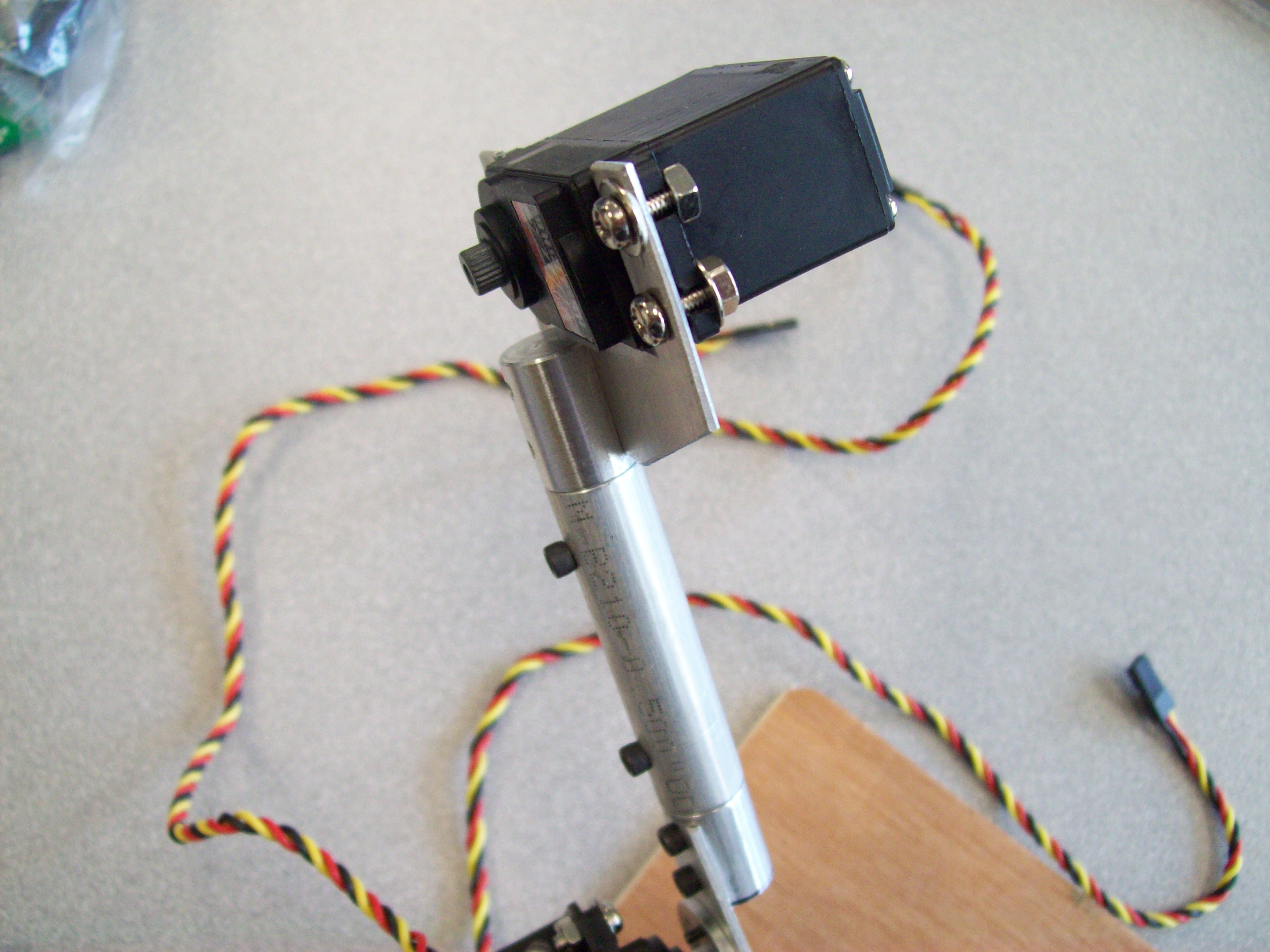
Finally, mount the third servo in reverse position onto the bracket as shown:
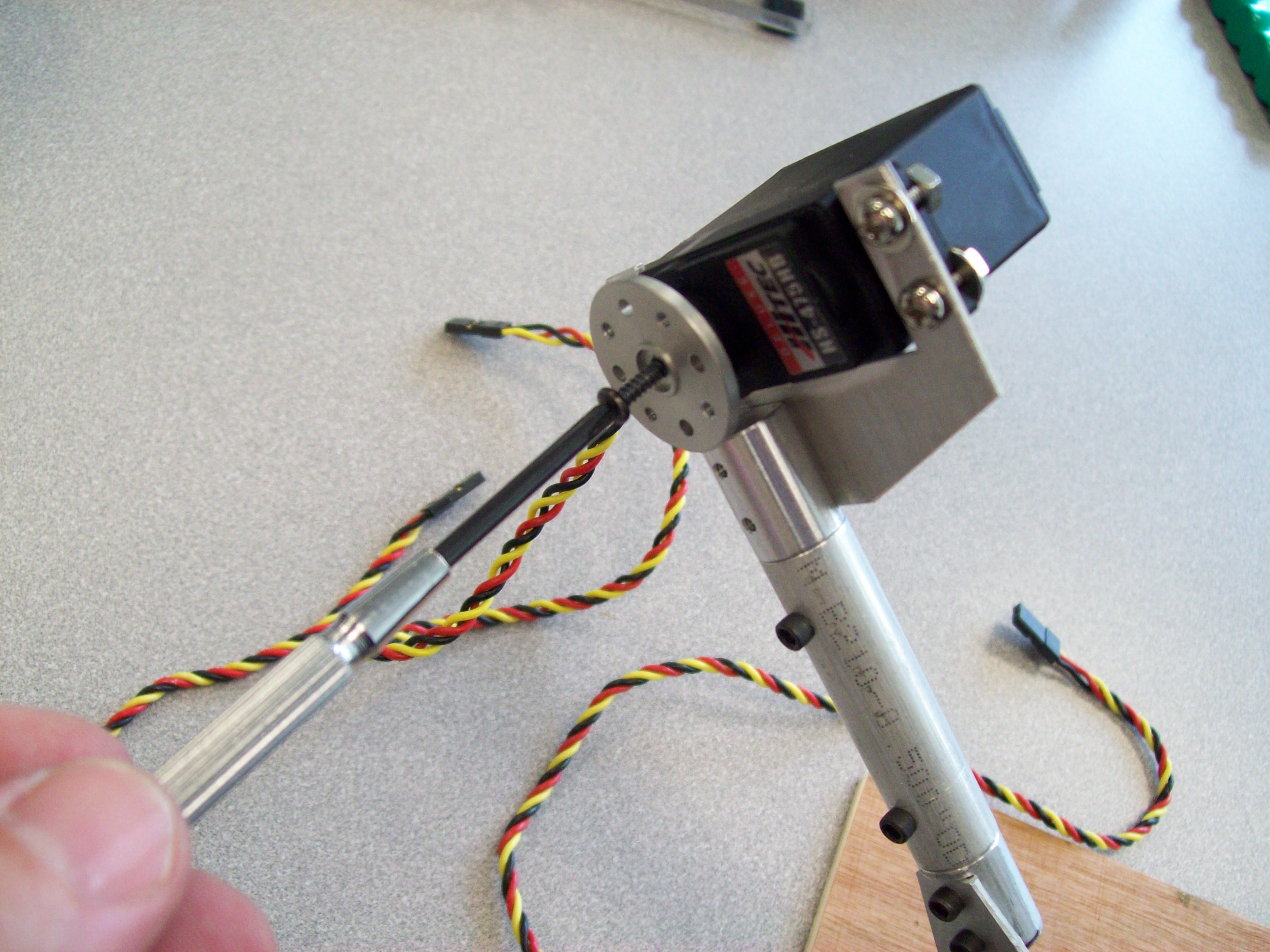
and using a center screw, affix a metal disk HMSH-02 to this third servo:
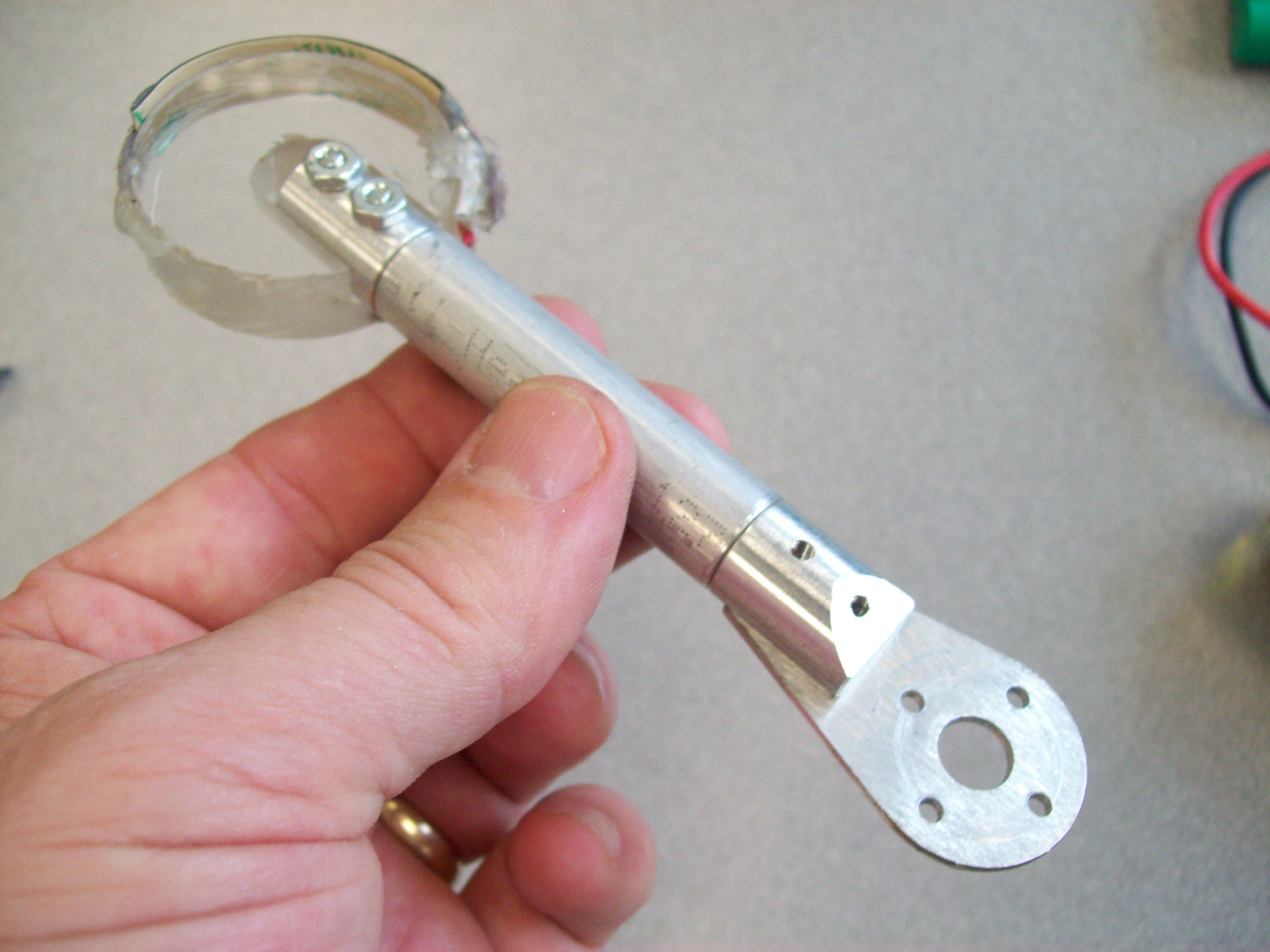
The completed "foot" assembly with sandpaper on the edge looks like this:
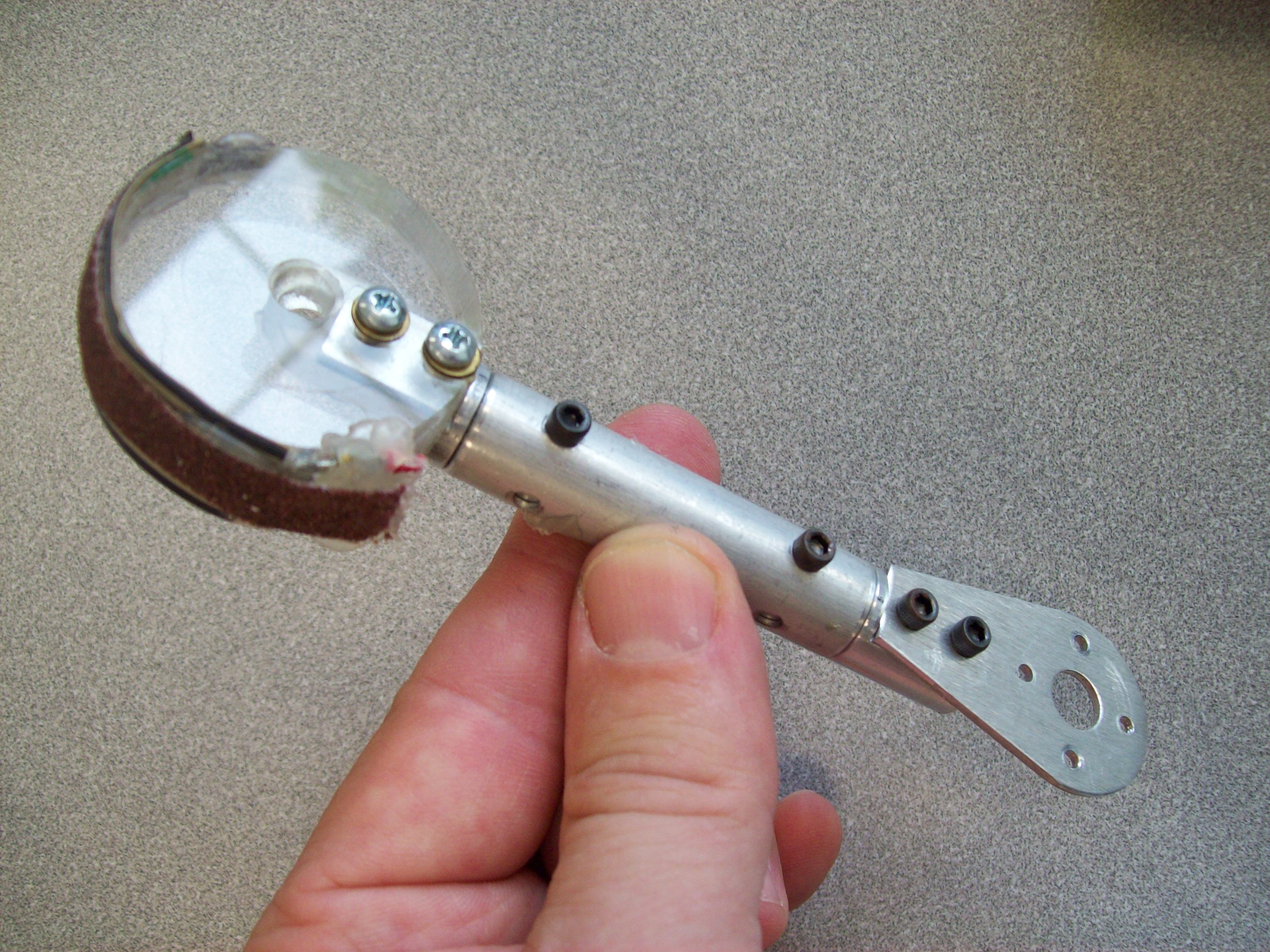
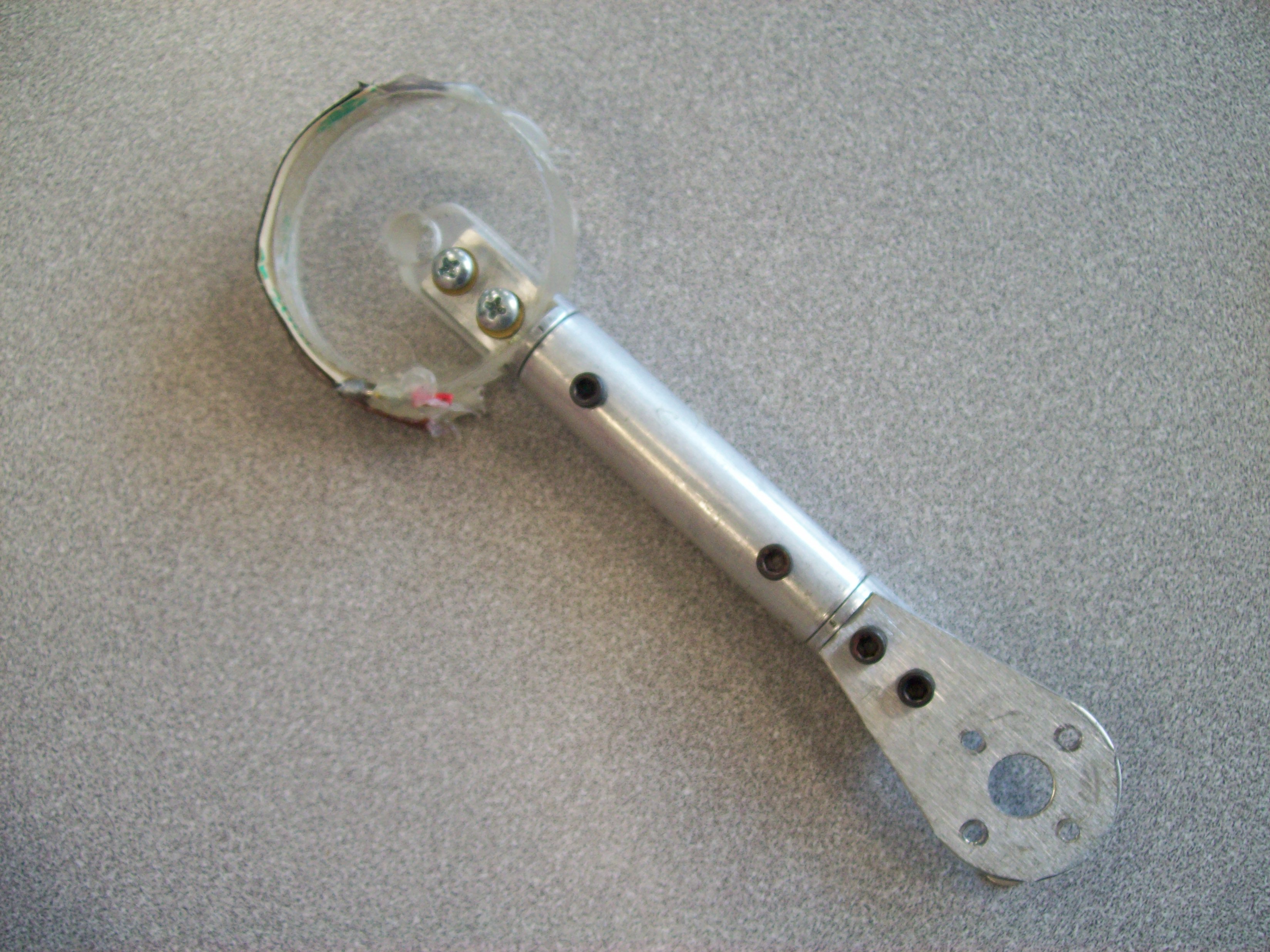
note that the HUB-09 at the elbow has to be sanded down a bit so that it won't collide with the screws holding the third servo:
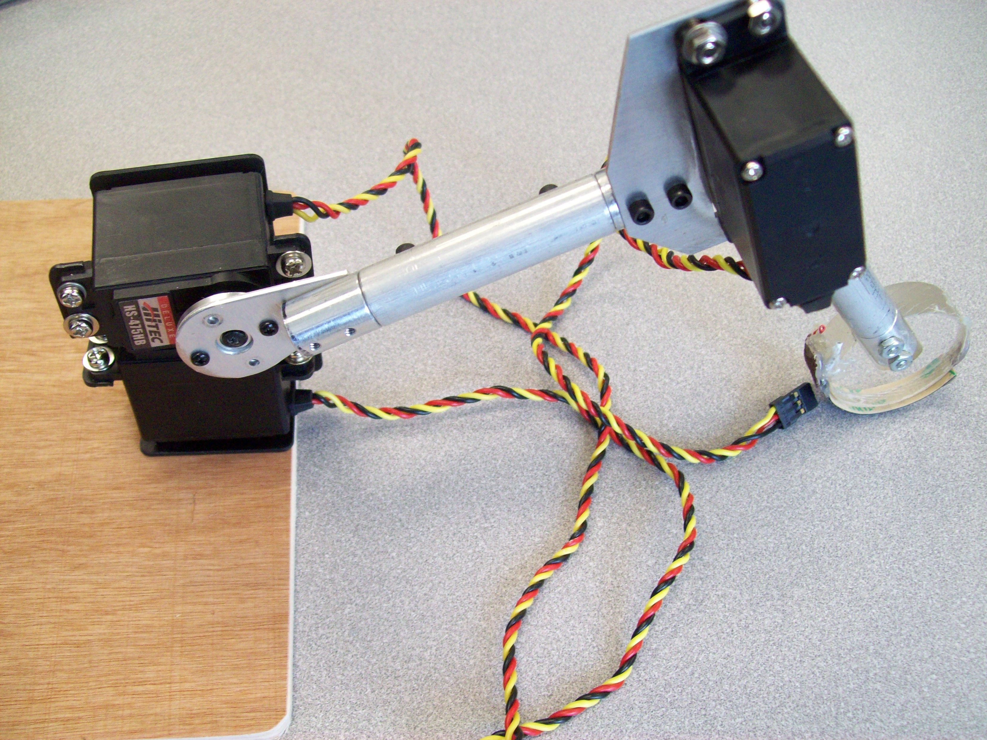
When the foot assembly is attached, it looks like this:
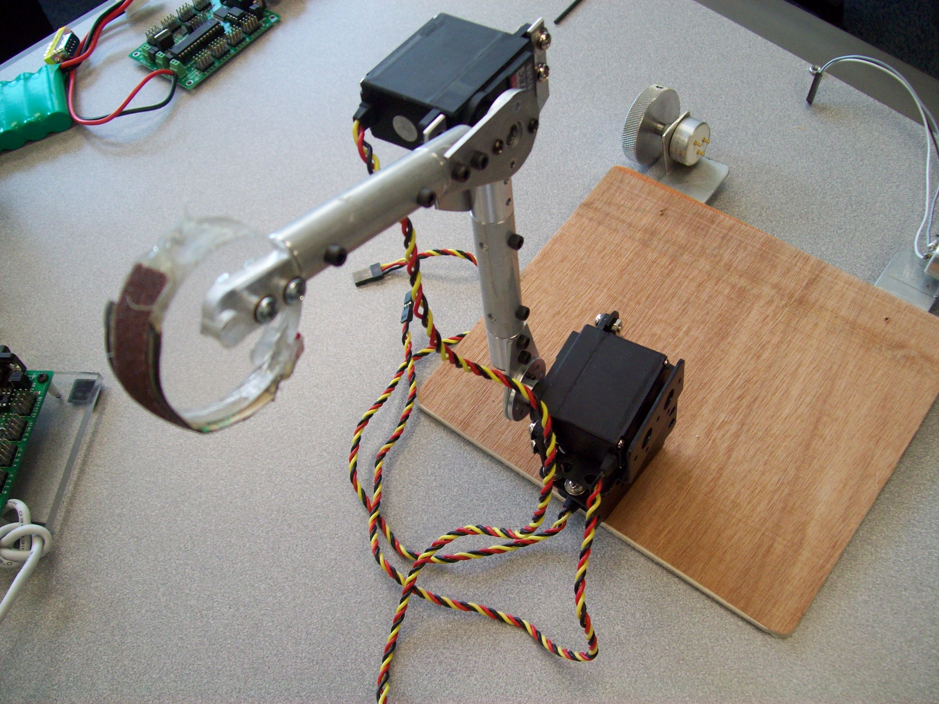
Once assembled, connect the three motor cables to a Lynxmotion board as before. Try booting up HyperTerminal and typing commands like "#0P1500" or "#1P2000" or "#2P800" and see if you can get the arm to move it all its directions. What are the limits to the range of each servo before the arm hits something?
|
Comments
or Questions? |
|
 |