ENGINEERING
11, 2004
ELECTRIC
CIRCUIT ANALYSIS
Lab 4 - BACKGROUND
An RLC circuit is shown below.
The response of this system can be solved for by using node equations. Assume a voltage, V’ between the resistor R and inductor L. Now writing the node equations at V’ and V0:
 (1)
(1)
and 
Solving the other node equation,  , for V’ and substituting into equation (1), yields
Second order systems are often characterized as follows:
where ![]() is the natural
frequency and
is the natural
frequency and ![]() is the damping
ratio. These terms result from the fact
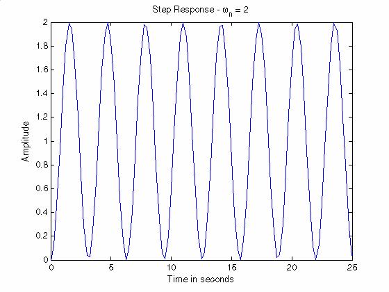
that if the damping ratio is zero, the system is an oscillator, and a unit step
input would cause an output that is a unit sinusoidal varying about 1 with
frequency
is the damping
ratio. These terms result from the fact
that if the damping ratio is zero, the system is an oscillator, and a unit step
input would cause an output that is a unit sinusoidal varying about 1 with
frequency ![]() radians/second. Shown
below is the step response
radians/second. Shown
below is the step response
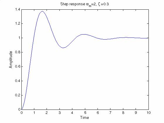
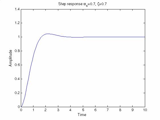
For a damping ratio between 0 and 1, the output is a damped sinusoidal and the rate of damping increases as the damping ratio increases. This situation is referred to as an underdamped system. If the natural frequency is unchanged, but the damping ratio is increased to say 0.3, the step response looks like
If the damping ratio is increased to 0.7, the step response is:
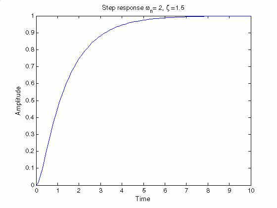
If the damping ratio is larger than 1, the system is said to overdamped. Below is the result with a damping ratio of 1.5;
where 

This is found by differentiating y(t) and setting it to zero.
The peak overshoot is found by evaluating V0(t) at the time to peak and subtracting 1.
Maximum overshoot as percentage is
The damping ratio for a particular %OS is